Search
Understanding the Final Shaping Process in FPC Manufacturing
- Sep 20,2024
-
Share
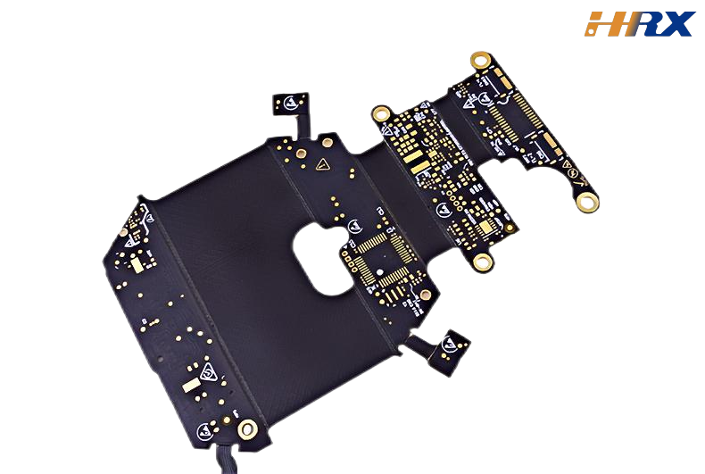
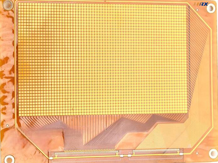
In the production of Flexible Printed Circuits (FPC), the shaping process is one of the last steps before final inspection and packaging. This stage is crucial as it ensures that every FPC product meets the design specifications, both in appearance and precision. FPCs come in various shapes—square, round, rectangular, tapered, or irregular—and the shaping methods must ensure uniformity, aesthetic appeal, and compliance with design requirements. Typically, there are three main shaping methods for FPCs: die-punch shaping, cutting, and manual shaping. The chosen method depends on factors such as production volume, precision requirements, and delivery timelines.
1. Die-Punch Shaping
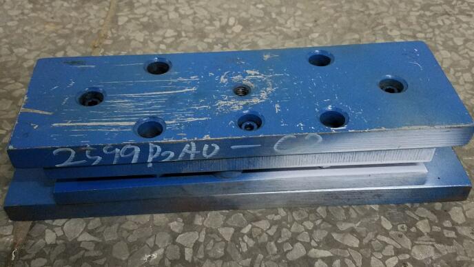
Die-punch shaping involves the use of molds, which are custom-made according to the specific FPC design. There are two types of molds based on materials: steel molds and knife molds.
Steel molds are the most common due to their durability and high precision. These molds are made from steel, which offers long-lasting performance and is resistant to deformation. Steel molds are commonly used for FPCs with a single board size of up to 600mm, as larger molds would increase costs due to the weight and complexity of installation.
Knife molds, on the other hand, are lightweight and cost-effective, typically made of wood with steel blades. However, they offer lower precision and are generally reserved for simpler products or auxiliary materials, such as reinforcement sheets.
Within the steel mold category, precision can vary based on how the mold is manufactured. There are three common production methods: wire electrical discharge machining (EDM), which can be classified into slow, medium, and fast.
Slow wire EDM produces precision molds with a tolerance of ±0.05mm. These molds are highly durable but are only used when strict precision is required due to their higher costs and longer production times.
Medium wire EDM results in standard molds, which have a tolerance of ±0.10mm. This level of precision meets the needs of most FPC designs, making it a popular choice for regular production.
Fast wire EDM creates simple molds with a tolerance of ±0.2mm. While these molds are less precise and slightly cheaper, they are usually chosen for products where appearance is not a critical factor.
The die-punch method involves placing the mold on a punching machine. The mold consists of an upper cutting die and a lower base. A test FPC is used to adjust the punching height to ensure the circuit is cut cleanly, without damaging unnecessary parts. Larger molds can often shape multiple FPCs in a single punch, significantly improving production efficiency. Once a mold is made, it can be reused as long as the FPC design remains unchanged, making it ideal for mass production and cost reduction per unit.

2. Cutting Shaping
Cutting shaping is generally reserved for sample production or very small batches. There are two primary methods: CNC cutting and laser cutting.
CNC cutting involves inputting the design into a computer and using a cutting blade to shape the FPC according to the design lines. The FPC is secured on the machine using positioning holes, and the cutting head moves according to the pattern. However, CNC cutting has several limitations: the cutting blades wear out quickly, affecting precision, and the process can be slow. Improper depth adjustments may result in excessive burrs or incomplete cuts.
Laser cutting has largely replaced CNC cutting in modern FPC manufacturing due to its higher precision (≤0.05mm) and cleaner edges. Laser cutting offers faster production times and fewer burrs, making it the preferred method for sample production. However, laser cutting can sometimes leave burn marks on the cutting edges due to the high-energy laser beams used. To maintain a clean appearance, it’s recommended to wipe the FPC with an alcohol-dampened, lint-free cloth after cutting.
3. Manual Shaping
Manual shaping is the least common method and is used only for products that do not have strict precision requirements. This process involves hand-cutting the FPC using scissors or knives. Due to the high variability in results, this method is typically reserved for non-critical applications or for very simple shapes.
Conclusion
The final shaping process of FPCs plays a critical role in ensuring the product meets both aesthetic and functional standards. Depending on the specific design, production volume, and required precision, manufacturers can choose between die-punch shaping, cutting shaping, or manual shaping. Die-punch shaping is the most efficient for large-scale production, while cutting shaping, especially laser cutting, offers excellent precision for samples and smaller batches. Although manual shaping is less precise, it remains a viable option for non-demanding applications.

Let’s talk! We’ll provide the perfect solution for you!
-
 Huaruixin Electronics mainly produces printed circuit boards as the core business, to provide customers with one-stop solutions for FPC/PCB production, components sourcing and Assembly.
 - WHAT WE DO — PCB Design Solutions — Flex PCB Production — Components Sourcing — FPC&PCB Assembly
- PRODUCTS — Single Sided Flexible Circuits — Double Sided Flexible Circuits — Multilayer Flexible Cirucits — Rigid-Flex Circuits — FPC Assembly — PCB Assembly
- CAPABILITY — FPC Capability — Rigid-Flex Capability — PCB Capability — Assembly Capability
- Copyright © 2024 Shenzhen Huaruixin Electronics Co., Ltd. All Rights Reserved.
- Design By BONTOP


