Search
Ensuring Adhesive Integrity in FPC Bending
- Mar 05,2025
-
Share
Flexible Printed Circuits (FPCs) have become an integral part of numerous industries, from consumer electronics to aerospace, owing to their remarkable flexibility and space - saving design. However, maintaining the integrity of the adhesive in FPCs during bending remains a persistent challenge in the field of Printed Circuit Board (PCB) manufacturing. Shenzhen Huaruixin Electronics Co., Ltd., a leading player in the production of FPCs, PCBs, and Rigid - Flex Printed Boards, has implemented a comprehensive set of strategies to tackle this issue head - on.

Material Selection
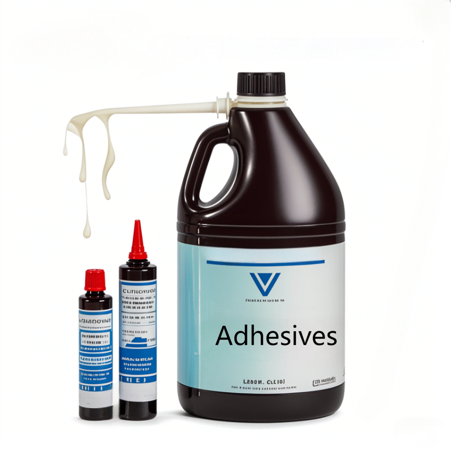
Adhesive
1.High - performance adhesive systems: The company strategically selects adhesives with advanced viscoelastic properties. For instance, modified acrylic - based pressure - sensitive adhesives (PSAs) are favored for their high peel strength, which is crucial for preventing delamination during bending. These adhesives typically exhibit a peel strength of over 15 N/cm, as measured by ASTM D1876 standards.
2.Low - modulus adhesive formulations: Adhesives with a low Young's modulus, such as certain silicone - based or polyurethane - based products, are preferred. A low - modulus adhesive can better accommodate the strains induced by bending. The Young's modulus of these adhesives is often in the range of 0.3 - 1.5 MPa, enabling greater elongation without cracking. This property is essential in ensuring the long - term durability of the FPC under cyclic bending conditions.
Substrate
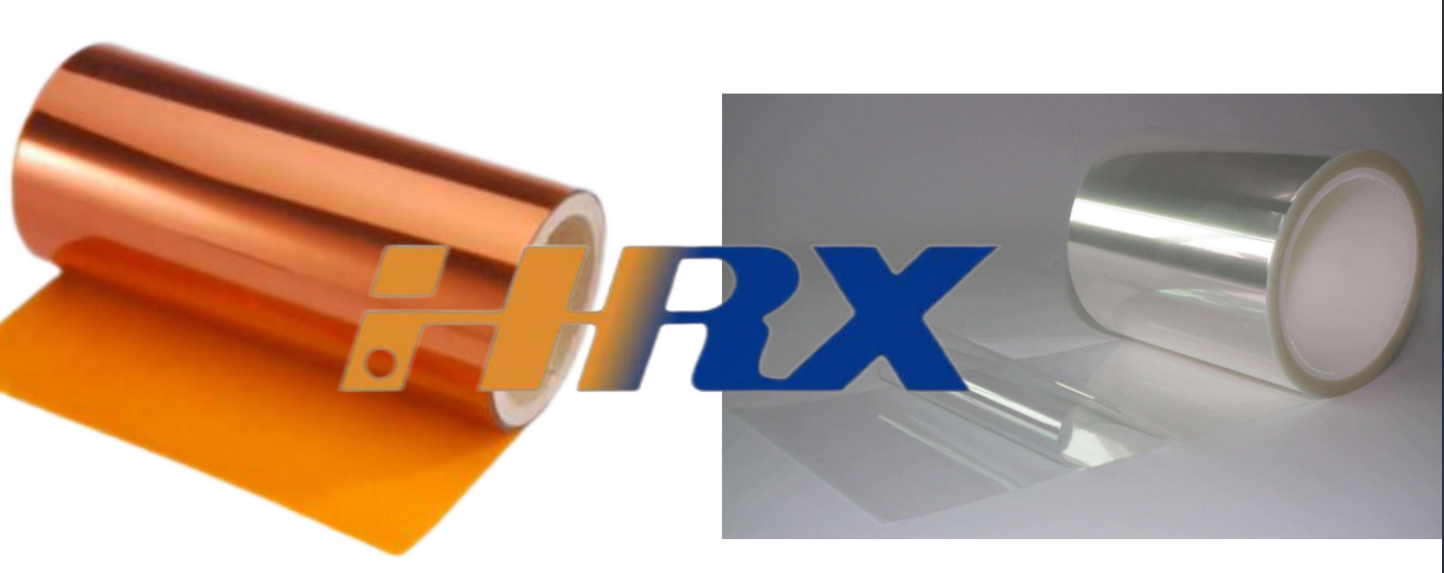
1.Premium polyimide substrates: Shenzhen Huaruixin Electronics utilizes high - grade polyimide films as the substrate for FPCs. Polyimide is renowned for its exceptional thermal stability, chemical resistance, and mechanical toughness. The polyimide films used typically have a thickness of 12.5 - 25 μm, which strikes an optimal balance between flexibility and structural integrity. This thickness range is carefully selected to meet the requirements of various applications, from wearable devices to automotive electronics.
2.Surface activation techniques: To enhance the adhesion between the adhesive and the polyimide substrate, surface activation methods are employed. Plasma treatment, for example, is a widely used technique that increases the surface energy of the polyimide film. After plasma treatment, the surface energy can be elevated to over 55 mN/m, promoting stronger bonding with the adhesive. This surface modification process is crucial for improving the overall reliability of the FPC.
Manufacturing Process
Coating
1.Precision coating technologies: The company employs state - of - the - art coating techniques, such as micro - gravure coating and slot - die coating, to achieve uniform adhesive deposition. Micro - gravure coating, for instance, can precisely control the adhesive thickness with a variation of ±0.5 μm. This high level of thickness control is essential for ensuring consistent performance across the entire FPC. In applications where strict dimensional tolerances are required, such as in high - density interconnect (HDI) FPCs, slot - die coating may be preferred for its ability to coat large areas with excellent thickness uniformity.
2.Adhesive thickness optimization: The optimal adhesive thickness is determined through a combination of theoretical analysis and experimental testing. For FPCs subjected to frequent bending, an adhesive thickness of 10 - 15 μm is typically selected. This thickness provides sufficient adhesion strength while minimizing the risk of stress concentration, which can lead to adhesive cracking. In some specialized applications, such as those involving extreme bending angles or high - frequency signals, the adhesive thickness may be further optimized to meet the specific requirements.
Lamination
1.Vacuum lamination process: Vacuum lamination is a critical step in the manufacturing process, as it ensures intimate contact between the adhesive and the substrate. During this process, a high - vacuum environment is created to eliminate air bubbles trapped between the layers. The vacuum level is typically maintained at 10⁻³ - 10⁻² Pa, resulting in a void - free laminate. This is particularly important for applications where electrical insulation and mechanical integrity are of utmost importance, such as in medical devices or military electronics.
2.Temperature and pressure profiling: Precise control of temperature and pressure during lamination is essential for achieving optimal adhesive curing and bonding. The lamination temperature is usually set between 150 - 200 °C, depending on the type of adhesive used. The pressure applied ranges from 5 - 10 bar. This combination of temperature and pressure promotes proper cross - linking of the adhesive and strong adhesion between the layers. In some cases, a multi - step temperature and pressure profile may be employed to ensure uniform curing and minimize internal stress.
Curing
1.Curing process optimization: A two - step curing process is often adopted to enhance the performance of the adhesive. First, a pre - cure at a relatively low temperature, around 80 - 100 °C for 15 - 30 minutes, is performed to initiate the curing reaction. This pre - cure step helps to reduce the viscosity of the adhesive and promote better wetting of the substrate. Then, a post - cure at a higher temperature, such as 180 - 200 °C for 60 - 90 minutes, is carried out to complete the curing process. This two - step curing process helps to minimize internal stress in the adhesive and improve its mechanical properties.
2.In - line curing monitoring: To ensure consistent curing quality, in - line monitoring techniques, such as infrared (IR) spectroscopy and dielectric analysis, are used. IR spectroscopy can be used to monitor the chemical reactions occurring during curing, allowing for real - time adjustment of the curing parameters. Dielectric analysis, on the other hand, can provide information about the degree of cross - linking and the mechanical properties of the adhesive as it cures. This data - driven approach to curing monitoring helps to improve the reliability and reproducibility of the manufacturing process.
Structural Design
Bend Radius Design
1.Minimum bend radius determination: Shenzhen Huaruixin Electronics calculates the minimum bend radius based on a comprehensive understanding of the material properties of the FPC and the adhesive. For a standard FPC with a polyimide substrate and the selected adhesive, the minimum bend radius is typically designed to be 0.5 - 1 mm. This value is determined through finite - element analysis (FEA) simulations, which take into account factors such as the mechanical properties of the materials, the thickness of the layers, and the expected bending loads. In applications where space is limited or where frequent bending is required, such as in foldable displays or robotic joints, the minimum bend radius may be further optimized to meet the specific design requirements.
2.Gradual bend transition design: In areas where bending is required, gradual bend transitions are incorporated into the FPC design. Instead of sharp bends, rounded corners or tapered sections are used to distribute the stress more evenly across the adhesive layer. The radius of the rounded corners is usually 0.2 - 0.3 mm, which helps to reduce stress concentration and prevent adhesive cracking. In some cases, a more complex bend transition design, such as a serpentine or zig - zag pattern, may be employed to further improve the flexibility and durability of the FPC.
Stress Relief Structures
1.Adhesive - free zones: In high - stress areas, such as near connectors or at the edges of the FPC, adhesive - free zones are created. These zones act as stress relief areas, preventing the build - up of excessive stress in the adhesive. The size and location of these adhesive - free zones are carefully designed based on the expected stress distribution in the FPC, which is determined through FEA simulations. In some cases, additional reinforcement materials, such as a thin layer of fiberglass or a metal foil, may be added in the adhesive - free zones to further enhance the mechanical strength of the FPC.
2.Reinforcement layer integration: In applications where high mechanical strength is required, reinforcement layers, such as a thin layer of carbon fiber or a high - strength polymer, are added to the FPC. These reinforcement layers help to reduce the stress on the adhesive by providing additional support. The thickness of the reinforcement layer is typically 5 - 10 μm, and its composition and structure are carefully selected to match the requirements of the specific application. In some cases, a multi - layer reinforcement structure may be used to provide enhanced mechanical performance.
Quality Control
Bending Testing
1.Advanced bending test equipment: The company is equipped with state - of - the - art bending test equipment that can simulate real - world bending conditions with high accuracy. The equipment can perform cyclic bending tests with a specified bend radius, angle, and number of cycles. For example, the bending angle can be set from 90° to 180°, and the number of cycles can range from 10,000 to 100,000. In some cases, the bending test equipment can also be used to perform dynamic bending tests, where the bending speed and acceleration can be controlled to simulate the actual usage conditions of the FPC.
2.Failure analysis techniques: After the bending tests, a comprehensive failure analysis is carried out on the FPCs. Visual inspection, microscopy, and other advanced techniques, such as scanning electron microscopy (SEM) and energy - dispersive X - ray spectroscopy (EDS), are used to identify the mode of failure, whether it is adhesive cracking, delamination, or substrate failure. Based on the failure analysis results, improvements are made to the material selection, manufacturing process, or structural design. In some cases, a root - cause analysis may be performed to identify the underlying factors contributing to the failure and to develop preventive measures.
Adhesion Testing
1.Peel strength testing: Peel strength testing is conducted in accordance with ASTM D1876 standards to measure the force required to peel the adhesive - bonded layers apart. The peel strength of the adhesives used in the FPCs is typically required to be above 3 N/cm. In some cases, a more stringent peel strength requirement may be specified, depending on the application. For example, in applications where the FPC is subjected to high - temperature or high - humidity conditions, a higher peel strength may be required to ensure the long - term reliability of the adhesive bond.
2.Shear strength testing: Shear strength testing is also performed to evaluate the ability of the adhesive to withstand shear forces during bending. The shear strength is tested using a shear test fixture, and the results are compared to the required specifications. In some cases, a dynamic shear strength test may be performed to simulate the actual shear forces experienced by the FPC during operation. The shear strength requirements may vary depending on the application, with higher shear strength being required for applications where the FPC is subjected to high - stress mechanical loads.
In conclusion, Shenzhen Huaruixin Electronics Co., Ltd. ensures the integrity of the adhesive in FPCs during bending through a holistic approach that combines advanced material selection, precise manufacturing processes, innovative structural design, and rigorous quality control. We welcome industry peers, both new and old, to engage in technical exchanges and collaborative learning to further advance the performance of FPCs in the global market.

Let’s talk! We’ll provide the perfect solution for you!
-
 Huaruixin Electronics mainly produces printed circuit boards as the core business, to provide customers with one-stop solutions for FPC/PCB production, components sourcing and Assembly.
 - WHAT WE DO — PCB Design Solutions — Flex PCB Production — Components Sourcing — FPC&PCB Assembly
- PRODUCTS — Single Sided Flexible Circuits — Double Sided Flexible Circuits — Multilayer Flexible Cirucits — Rigid-Flex Circuits — FPC Assembly — PCB Assembly
- CAPABILITY — FPC Capability — Rigid-Flex Capability — PCB Capability — Assembly Capability
- Copyright © 2024 Shenzhen Huaruixin Electronics Co., Ltd. All Rights Reserved.
- Design By BONTOP


