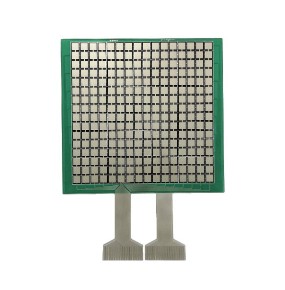
In the world of electronics, FPC (Flexible Printed Circuit) sensor boards play a critical role in various applications, from touch panels to wearable devices. These sensor boards often feature matrix configurations such as 16x16, 32x32, or 64x64 sensor arrays. Each configuration offers its own balance of resolution, performance, and application-specific benefits. In this blog, we’ll explore the key design considerations for FPC sensor boards, focusing on 2-layer designs, sensor connections, and best practices for optimal performance.
1. Matrix Design for FPC Sensors
Uniform Sensor Size & Spacing
When designing FPC sensor boards, maintaining uniform sensor size and spacing is essential for consistent signal processing and accurate data capture. Whether it's a 16x16, 32x32, or 64x64 matrix, ensuring that each sensor is evenly spaced and sized ensures uniform sensitivity and detection across the entire array.
· 16x16 Matrix: Typically used in applications that require lower resolution but greater speed, such as simple touch panels or proximity sensors.
· 32x32 Matrix: A middle ground, offering higher resolution without a significant increase in complexity or cost, making it ideal for mid-range touch or motion detection applications.
· 64x64 Matrix: Suited for applications where high precision and fine resolution are necessary, such as medical or industrial equipment.
Impact of Resolution & Sensor Sensitivity
The choice between 16x16, 32x32, or 64x64 matrices directly impacts resolution and sensitivity. Higher resolution matrices (like 64x64) offer greater detail but can be more complex to design and manufacture, whereas smaller matrices (like 16x16) are simpler but may sacrifice detail. The choice should depend on the intended application’s need for precision versus processing speed.

2. Layering Considerations: 2L FPC Design
2-Layer FPC Construction
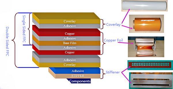
Most FPC sensor boards utilize a 2-layer construction, which balances flexibility with robust signal routing. The dual layers allow for easier signal management and reduce interference, which is crucial when working with complex sensor arrays.
Signal Tracing and Routing
In 2-layer designs, signal integrity is paramount. Proper signal tracing and routing prevent noise and crosstalk between adjacent signals, which is especially important in high-density configurations like 32x32 and 64x64 matrices. Designers should also pay attention to minimizing the resistance and capacitance across the signal paths, ensuring smooth operation.
3. Gold Finger and Connector Interface Design
Gold Finger Design and Durability
The gold fingers on an FPC board provide the connection interface between the sensors and external circuitry. These gold-plated contact points must be designed for both durability and reliability, as they are repeatedly inserted and removed from connectors in many applications.
· Durability Considerations: The thickness of the gold plating should be sufficient to withstand mechanical wear, especially in applications where frequent connection cycles occur.
· Connection Integrity: Poor alignment or mismatched connectors can result in signal loss or intermittent failures. Ensuring precise design and compatibility with industry-standard connectors is crucial.
Connector Matching
Proper matching between the FPC’s gold fingers and the connector is essential for reliable signal transmission. Designers must ensure that the connector is properly aligned with the gold fingers, minimizing signal degradation and mechanical wear.
4. Key Applications of FPC Sensor Boards
Touch Panels and Wearables
In consumer electronics, FPC sensor boards are widely used in touch panels for smartphones, tablets, and wearables. Lower-density matrices like 16x16 are often sufficient for these applications, where speed and responsiveness are more critical than ultra-high resolution.
Medical Devices and Industrial Equipment
For more precise applications such as medical devices and industrial controls, higher-density matrices (32x32, 64x64) are often required. These FPC sensor boards must be highly reliable and resistant to environmental factors like moisture, heat, and vibration.
Automotive and Aerospace
In extreme environments like automotive and aerospace applications, FPC sensor boards need to withstand high levels of stress, temperature variation, and vibration. Here, robust 2L designs with appropriate reinforcements and thermal management solutions are essential.
5. Design Testing and Prototyping
Prototyping Best Practices
When developing an FPC sensor board, rapid prototyping is crucial for testing different matrix configurations and identifying potential design flaws early. Designers should focus on iterative testing to ensure the sensor array meets the performance requirements.
Testing for Performance and Reliability
To guarantee that the final product performs as expected, thorough testing is necessary. This includes mechanical stress tests, thermal analysis, and signal integrity tests to ensure the FPC board can handle real-world applications.
Designing FPC sensor boards with matrix configurations like 16x16, 32x32, or 64x64 requires careful consideration of sensor size, spacing, and connection methods. By focusing on uniformity, signal integrity, mechanical durability, and thermal management, engineers can create sensor boards that meet the specific demands of their target applications. As technology advances, these designs will continue to play a pivotal role in enabling more innovative and efficient products across industries.

 Huaruixin Electronics mainly produces printed circuit boards as the core business, to provide customers with one-stop solutions for FPC/PCB production, components sourcing and Assembly.


